Sunday 1 June 2014

Cara Membuat Linear Dimension dalam AutoCAD

Salam Hangat di Awal Minggu..

Memberi ukuran dan menyajikan sebuah gambar lengkap dengan ukuran ukuran baik panjang maupun lebar,tinggi dsb,sangat diperlukan dan dibutuhkan bagi pengguna gmbar maupun orang yang menggambar itu sendiri ( drafter ),untuk itu kita menggunakan tool bar yang disebut dimension tool.

Pada awal pembahasan terdahulu saya sudah mengulas bagaimana cara merubah skala dimensi dalam autocad atau cara menggunakan dimensi tool,jadi selanjutnya saya akan mencoba mengulas dan membahas bagaimana cara membuat linear dimensi atau cara menggunakan dimensi linear dalam autocad, how to create linear dimensions using AutoCAD, nah Sebelum membuat linier dimension pada Autocad, harus pahami terlebih dahulu fungsi dari linier dimension itu sendiri. 


Linier dimension adalah salah satu tool yang digunakan untuk memberi ukuran pada garis horisontal dan juga vertical.


Adapun cara membuat linear dimensi dalam autocad ada beberapa cara :

Pertama buatlah sebuah rectangle dengan ukuran 100x150.
Klik ikon linear dimension pada toolbar atau ketik Dimlinear → Pilih titik pertama dan kemudian titik kedua dst. → enter.


Beberapa pengaturan dan modifikasi langsung dalam linear dimensi :

1.Mtext.
Merubah secara langsung text dalam linear dimensi,yang berupa jenis teks,besar dan kecilnya teks dsb seperti kita merubah sbuah teks.

Caranya : Klik ikon linear dimension pada toolbar atau ketik Dimlinear → Pilih titik pertama dan kemudian titik kedua dst. → pilih Mtext atau ketik M → rubahlah jenis font,besar kecilnya teks dan warna teks → klik OK/Enter → klik di tempat yang di inginkan.


2.Text.
Merubah secara langsung text dalam linear dimensi,yang berbeda dari semula.

Caranya : Klik ikon linear dimension pada toolbar atau ketik Dimlinear → Pilih titik pertama dan kemudian titik kedua dst. → pilih Text atau ketik T →Masukan nilai ukuran yang di inginkan → klik OK/Enter → klik di tempat yang di inginkan.


3.Angle
Merubah secara langsung letak sudut text dalam linear dimensi,yang berbeda dari semula.

Caranya : Klik ikon linear dimension pada toolbar atau ketik Dimlinear → Pilih titik pertama dan kemudian titik kedua dst. → pilih Angle atau ketik A →Masukan nilai Sudut  yang di inginkan → klik OK/Enter → klik di tempat yang di inginkan.


4.Horizontal
Merubah secara langsung peenmpatan titik  ukur berdasarkan garis tegak lurus atau garis horizontal.

Caranya : Klik ikon linear dimension pada toolbar atau ketik Dimlinear → Pilih titik pertama dan kemudian titik kedua dst. → pilih Horizontal atau ketik H →Masukan nilai Tinggi garis ukur  yang di inginkan → klik OK/Enter .


6.Vertikal
Merubah secara langsung penempatan titik ukur berdasarkan garis Mendatar atau garis Vertikal.

Caranya : Klik ikon linear dimension pada toolbar atau ketik Dimlinear → Pilih titik pertama dan kemudian titik kedua dst. → pilih Vertikal atau ketik V →Masukan nilai Tinggi garis ukur  yang di inginkan → klik OK/Enter .
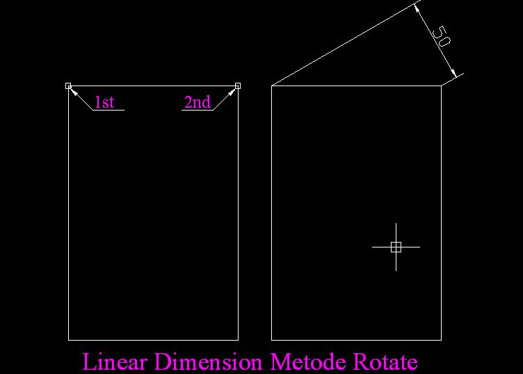


7.Rotate
Merubah secara langsung letak garis ukur sesuai dengan keadaan benda.

Caranya : Klik ikon linear dimension pada toolbar atau ketik Dimlinear → Pilih titik pertama dan kemudian titik kedua dst. → pilih Rotate atau ketik R →Masukan sudut kemiringan yang di inginkan → klik ditempat yang dituju.


Demikian cara membuat linear dimension atau cara mengukur menggunakan dimensi linear,cara membuat dimensi garis atau terkenal dengan istilah linear dimension ini sangat dibutuhkan dalam proses pembuatan gambar dan penyajian gambar terutama dalam hal pemberian ukuran.

Semoga tutorial singkat bagimana cara membuat linear dimensi ini dapat bermanfaat khususnya bagi saya pribadi dan tentunya bagi rekan rekan semua yang sedang belajar menggambar menggunakan autocad baik di tempat kursus maupun yang belajar sendiri – sendiri atau privat.
http://www.we-r-here.com/cad/tutorials/level_3/adding-materials-to-3d-objects-autocad-3-9.htm

Conversion from mesh into solid (part 1)

One of the most exciting options in the new Mesh modeling commands is the ability to convert a mesh into a solid or a surface. It is really a differentiator, since we can handle different topologies, and have workflows among them.
Once the mesh is converted, it can be manipulated with the Autodesk Shape Manager (ASM), which means that Boolean operations (Union, Subtract, and Intersect) and other operations for solids can be performed.
There are four options for converting to either solid or surface, which are smooth optimized, smooth not optimized, faceted optimized and faceted not optimized. Why so much choice? As a user, do I need to care? In fact, you do, if you want to take advantage of the whole power of this operation.
Let’s start with Convert to Solid.
In order to convert into a solid, we will use the command CONVTOSOLID, or access it from the Ribbon (it is located in the Mesh Modeling tab, in the Convert Mesh panel.
Convert Mesh panel in the Ribbon
In order to be successful in the conversion into a solid, the object must comply with a couple of conditions. It has to be a watertight structure, which means that there should be no gaps in the model. If there’s a gap, then the operation will not be successful. The example below shows a mesh with a gap. It was done with a revolution, and as you can see, it is not closed. This is the kind of mesh that won't get converted into a solid.
Mesh with a gap

The object can’t self intersect. Self intersections may happen really easily with all the flexibility and power for manipulation that our tools provide. The whole point is that you may not care, if you are going to remain as a mesh. We have already explained how mesh modeling is much more pervasive in the media and entertainment side, and in those cases, fabrication is not an issue. But when we try to create a solid, self intersection is not acceptable.
This is a clear example of self intersecting mesh.
Self intersecting mesh
The first option that appears in the right side of the panel will be by default Smooth Optimized. We’ll focus on this option today.
Smooth Optimized will create a smooth solid, and AutoCAD will attempt to stitch faces with G2 continuity. That ensures a solid with the least amount of Nurbs patches. This is especially useful when exporting into Revit. But we’ll leave that for other posts.
 I will show a couple of examples that may help understand how much we can optimize the amount of Nurbs patches. It will also help to keep in mind how to proceed when doing mesh modeling. If the final destination is Revit, we will want a low number of patches. If we will remain in AutoCAD, you don’t need to care!
In this first example, I started with a box, increased the smoothness level to 2, and did some manipulation of edges and faces.
Box with smoothness level 2 and some manipulation
When the model is converted into solid, it has 6 patches, which is the least amount of patches that a box can have.
Optimized solid
When a crease is applied on the edges of an object like in the example below, you will notice that the solid has one more patch, in order to solve the creasing. Since creasing is basically affecting the continuity, it seems quite obvious that there will be an effect on the way AutoCAD converts into a solid.
Mesh with creased edges
Once we convert into solid, it is still worth noting how the conversion still provides a low amount of patches in the rest of the solid.
Mesh converted into a solid
In the next example, I creased all the faces at the bottom of the box.
Mesh with bottom faces creased
This is a pretty obvious case when modeling a building that may normally need to be firmly based on the ground. Something similar happens with the patches in the solid. In the previous examples, more patches were created next to the creasing. The same thing happens here. You’ll notice a second row of patches, simple because of the fact that the creasing affected all the faces at the bottom, thus having an effect over the whole ring of edges.
Mesh converted into a solid 
Another case to take into consideration is when you refine the mesh. If the refinement is done for the complete model, it will behave pretty much in a similar way to the first case.
This is a basic mesh primitive (box) that was refined when in level 2. 
Mesh refined 
The solid created with Smooth Optimized is exactly the same as if we had used the primitive in Level 2 with no refinement. 
Mesh refined converted into solid
AutoCAD can really make a good optimization of the faces in the mesh. You can see this in the example below.
In this case, we'll refine the box and make some manipulaitons that add more complexity to the overall shape.
Same mesh with manipulation
After refining and manipulating faces, we still have 6 patches!
Conversion into solid
However, if we refine a specific part of the model, the optimization will be less predictable. Refining selection is in my opinion a very interesting way for working with less faces, and only adding complexity where needed. As I said before, you may or may not care about the amount of Nurbs patches in the object.
This is the mesh with a couple of faces refined.
Refine by selection 
The resulting solid has much more patches.
Resulting solid with many patches
There’s a lot more to cover, but we’ll keep it simple now, and elaborate in following postings.

Back to basics: Extrusion in AutoCAD part 4

The last option to cover within Extrusion is Path. This will take four complete posts, but I think it’s worth examining the options very carefully.
Last time we talked about Direction, which would somehow do the same as Path, if the latter was a simple segment. If you have a polyline, 3dpolyline or spline, then Path is the right option.
Let’s see how it works.
First of all… where do we locate the path? Well, there are some rules for that.
Normally, the path will be located in a point that touches the profile. The path does not need to actually start in the profile, but it normally helps to better understand what you are doing. However, this may vary. You could have the path starting at a midpoint in one of the segments of the profile, or even have the path starting anywhere, and at some point intersecting the profile. Actually, the command will also work with a path which does not touch the profile! The result may not be too predictable, but there’s always a rule for that too (but not today).
000 
Let’s assume that the path starts at the bottom vertex of this rectangle. Once we invoke the Extrude command, we need to add the path, since what we’ll see by default is the dynamic preview of the profile extruding along its normal. Once we access Extrude options (down arrow, right click if you use mouse sensitivity, or command prompt), we select Path, and then click on the entity which will act as path. And voila!

 001 
This is the before and after selecting the path (images above and below respectively)
002 
Let’s see what happened in this process. If we go to a Top View, we’ll see that the angle between the profile and the path was kept. I have heard people asking why (in a similar case) the ending of the extrusion is not vertical. Well… that’s not the way the command works. If you need something like that, a loft between two profiles and a guide would be better.
003 
Does this work in any case? Let’s try with this other arc, which starts almost tangent to the profile. Almost is the magic word here. Since it is not tangent, the command works perfectly, as you can see in the two images that follow.
004
005

 
In the following image, we can see a scenario where the command will fail. The path intersects the profile, and it will be impossible not to generate a self intersecting solid. That’s something that AutoCAD will not accept. Some applications can force the creation of a non valid solid, but that will lead to problems at some point.
007
 
One last case for today. The following path and profile don’t have any trouble in creating an extrusion. But if we move the path to the other end of the profile, it will fail, since the path’s curvature is smaller than the length of the profile, which will evidently cause a self intersection. Pretty obvious, but tends to happen, and sometimes in the middle of a very long day, we may oversee this kind of conditions that Extrude with Path needs for a successful operation.
In the two images that follow, the command succeeds, while it fails with what seems a small change in the starting conditions (last image).
008
009

 010

Back to basics: Extrusion in AutoCAD part 5

So, now that we know how to use Path for the extrusion, let’s do some direct manipulation on the extruded object.
100 
Let’s start by clicking it and see what we can do. We’ll see grips for the profile, grips for the path (in this case an arc), and another grip for position of the model. It is important to understand that there is no associativity between the arc and the object. The grips belong to the model, although they will be coincident with those from the arc before you make any changes.
101 
In the following image you will see what I mean. As soon as we use that grip (center grip along the path), the curvature changes, and once we finish the operation, the arc is still in its place. After the operation, the arc is not relevant for the model itself.
102 
The grips that belong to the profile can be moved very easily by using the Gizmo, into pretty much any shape that does not create self intersections. In this case, I just moved one vertex up, and the AutoCAD reacted in a very predictable way (for an extrusion). If you just wanted to move that vertex up, then there’s an extra step (use the command BREP). But that’s another post for another time.
If we were doing some very basic conceptual design, even after doing the extrusion, we have the chance to adjust the volume to another object. In this case, I’m moving the grip so as to be coincident with the height of the adjacent box, and that’s it. No need to worry at the beginning of the design. You can be as flexible as you want.
104 
105

 
Now, I’ll just leave you with the final image. Just wanted you to know it was done with just two more clicks. Wonder how? Yes… you got it. That’s another post.
107 

Defining AutoCAD Camera

  1. Create your model. I will not go there, at least not for now. You can use your own model or use the same model with me. Click here to download the DWG file.
  2. Set up your camera view, that will be discussed in this article.
  3. Set up lighting, which can be divided to two categories: natural and artificial lighting.
  4. Set up materials.
  5. Set up rendering configurations.
The first thing we are going to do is setting up our camera view. Type CAMERA and press [enter]. Click first point as camera location, then second point as camera target.
camera_placement
After you place the camera, AutoCAD will give you several options. Give the camera name. Use a name that clearly describe the camera purpose and location. If you have many cameras in your model, you will be grateful that you name it properly.
camera_name
Don’t worry about the other options. We will change them later. To work in 3D easier, it would be more convenient to have several view angles in our viewport. Now let us configure the viewports. Click viewport configurations, then choose 2 or 3 viewports. Feel free to choose which one you feel more convenient.
viewport_configurations
I choose 3 viewports so I can view the model from top, front, and right side.
AutoCAD_viewports
Now select the camera. Cycle between objects by holding [shift] then press [space] several times until the camera is highlighted.
After you select the camera, you should see a camera preview like below.
camera_preview
Now look at your camera. There are several grips that you can use to control the camera location, camera position, camera target, and lens length (FOV).
Move your pointer above at the grip, wait for a while. Now you can see the gizmo or coordinate axis moved there. I’m not sure if we call it gizmo in AutoCAD, but 3ds Max users do.
grip_control
Move your pointer to any axis, then can see an infinite thin line at the axis. It means the axis is locked. Click and hold your left mouse button, and drag the grip to new position. By using this method, you can easily move the camera grips along any axis, without having to view the model from different angle. But sometimes you need to move to other viewport to move it easier.
You can also click the grip to select it and move it like you move any other AutoCAD object.
Feel free to place the camera and target. Choose the place you feel the best for you. You can also change the camera properties by changing the coordinate in properties palette. Try to change the roll angle and have fun!
camera_properties
Now after you have done, you can select the camera, right click, and choose set camera view from contextual menu. Your viewport is now showing your camera view.
Now change the visual styles to shading, hidden lines, or anything that will show the solid form. We need to do this to check if the camera is showing the model correctly.
visual_styles_panel

Setting Up AutoCAD Sun Light is Easy!

Do you think setting up lights for AutoCAD rendering is difficult? Or do you think trial and error for setting up AutoCAD lights take too much time? Not really. In this rendering tutorial, you will learn to setup the sun light easily and a little trick to speed up the rendering test. This is the second part of our rendering tutorial. We have defined our camera view in previous tutorial. Next, we are going to define the AutoCAD lighting. We will discuss sun light (or natural  lighting) and artificial lighting separately. Sun light comes first. Lighting is one of the most important thing in rendering.
If you already downloaded the DWG file from the previous tutorial, I apologize. I forgot to add floor to the model, you can download this one to continue with this tutorial. And of course, you can use your own model.

Turning Off Materials

Why not we define the objects’ material first? Setting up rendering light can take a lot of time. You need to do several rendering tests until you get what you want. Having your materials defined already, will make the rendering slower. Especially when you have many reflective and transparent materials. With no materials defined, the rendering will be faster to get the proper lighting. After we satisfied with the lighting, then we define the materials.
First, we need to turn the material off. Go to render tab, materials panel. Check if the materials/textures off. Turn it off if it’s still on.
material_off
This is a pretty simple model. If your model have several windows or opening, you can try to set the light to come through from your preferred opening/window. Our objective is to get the solar light come through from the window, and in this model we only have one. So let’s turn off the window’s glass layer. In this file, the layer would be 3D-GLAZ-GLAS.
The next layers you are going to turn off is totally up to you. In very complex model, it would be wise if we turn off objects that is not too important in setting up lights. If you have powerful machine and working on a relatively small model, you may not feel the difference. But when you have a bit old machine and the model has many geometries, then this can help. This model is quite simple, but let us hide the furniture to set up our lighting fixtures. Leave the wall, ceiling, and floor layers on.

Geographic Location

To define the solar light properly, we need to set the geographic location. Click set location in Sun & Location tab.
set_location
AutoCAD will give you options how you want to define the location. For this tutorial, choose enter location values. We will have another dialog box opened. You can define the location by typing the latitude and longitude. Or simpler way to do it is by using use map.
geographic_location
Pick your location and click OK until all dialog are closed. I use Jakarta as my location. Your result will look different if you choose other location. But it doesn’t matter.

Sky and Sun Properties

Now let us turn on the sky. If we don’t turn it on, the sky will be black. Not so nice for daylight rendering, right?
sky_properties
Next, let us set the sun. click the sun status icon.
sun_status
When you do it for the first time, AutoCAD will give you some options. Choose to turn off default lighting. Default lighting is ugly. We are going to use natural light from the sun. After you turn off the default lighting, you could see the date and time slider active.
date_and_time_setting
Turn on shadows. Change the setting from no shadows to full shadows.
shadows_setting
Now try to change the date and time until you can see the sun light come through the window. Do it until you feel the light angle is good. In photography, morning and afternoon sun light is considered as the perfect time. It gives a great lighting depth and covers wider area than when the sun right above your head.
shadow_appearance

Rendering test

We are going to test our light settings, but this is not a final render yet. So you can use lower quality to render it. I suggest you to try on medium quality. Draft and low quality give very rough lighting effect. Medium quality is more relevant. Click the small arrow on the lower right of render panel to open advanced render settings.
advanced_render_setting
In the advanced render settings, change the render quality to medium. And find indirect illumination category in that palette. Click the light bulb next to global illumination to turn it on.
global_illumination
Without indirect light, we will not see the effect of the bouncing lights. Turning it on will make the rendering longer. If you are experienced, you may be able to predict the final result without turning it on. But let us try with the indirect light on. Click render and wait a few minutes to see the result.
initial_render
I think this is nice. Now let us adjust the exposure. This is totally up to you. I feel the render result is not bright enough, and not enough contrast. So I will adjust them. Click adjust exposure to open the dialog.
adjust_render_exposure
AutoCAD will open a dialog. There are several settings that you can change to make the rendering result nicer. You can click the up and down arrow or simply type new value. The preview window will update as soon as you change the values. Do it until you feel it’s good enough.
adjust_rendered_exposure_dialog
Now let us test the rendering again. This is what I get. Better, right?
after_adjust_render_exposure
Remember, in the real rendering setup, you may need to do several trial before you get satisfied result. And finally, after we feel it’s nice enough, test it with your objects on.
Not bad, isn’t it?
If you are using your model, and have different result with mine, I would like to see how it looks. And I believe the others would like to compare with theirs. So put in on you blog, FlickrPhotobucketCAD Notes facebook page, or anywhere people can see it. Share the link to your rendering result using the comment form below.
Aren’t you feel excited how the result would looks like? Keep following this tutorial! We will do it together!